Flight Guidelines for Shading Analysis
Image capture for shading analysis requires flights to provide four types of images:
- Mapping
- Orbital
- Outward oblique
It is best to perform this inspection when trees have sufficient foliage for image capture and analysis.
EQUIPMENT & SETTINGS
Drone: Capture images with a multi-copter UAS with gimbal mounted camera. A DJI Phantom 4 Pro is the preferred drone for this purpose.
High-resolution camera: 5472×3648 pixel (20 MP) resolution minimum as provided by, for example, the Phantom 4 Pro or Zenmuse X4S cameras.
Images must be JPEG and contain metadata (GPS, relative altitude, gimbal altitude, and timestamp).
GCPs: Ground control points must be used for this inspection type.
Propellor Aeropoints is the easiest way to collect GCPs.
Make sure site is in the Propellor Corrections Network
Follow these instructions to download a copy of the user manual.

From propelleraero.com Aeropoint Manual
Manual GCPs:
These need to be identifiable and surveyed GCPs meaning that the position and elevation are known precisely typically using a correction network and the GCP can be easily identified from nadir drone imagery.
GCPs may exist on the site already from construction or other surveys, which can be used if they can be easily identified from nadir drone imagery. If using pre-existing GCPs we need to know the coordinate reference system (aka datum) used.
Required Datum:
Data must be captured in the following coordinate system:
Horizontal datum: to be specified on a per-project basis
Vertical datum (USA): NAVD 88 elevation Vertical datum is critical. Contact Raptor Maps if you require further instructions on setting AeroPoints to this elevation.
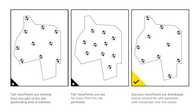
GCPs should be on the ground and distributed evenly around the perimeter with remaining GCPs distributed evenly in the center.
Do not make GCPs on top of an inverter or other onsite equipment.
If data is submitted not according to the standards listed here, a re-flight may be required at the expense of the drone service provider.
MAPPING FLIGHT
Resolution & altitude:
2 cm/pixel (.8 in/px)
Approximate altitude: 91.4 m (400 feet) above ground level (AGL)
Gimbal pitch:
Nadir (straight down)
-90 degrees from horizon
Overlap:
75% front overlap, 75% side overlap
Flight area:
The flight path should cover the entire site including neighboring tree line with a grid flight pattern
ORBITAL FLIGHT
Altitude:
Altitude: Approx. altitude should be 250 ft above the tree-line
Gimbal pitch:
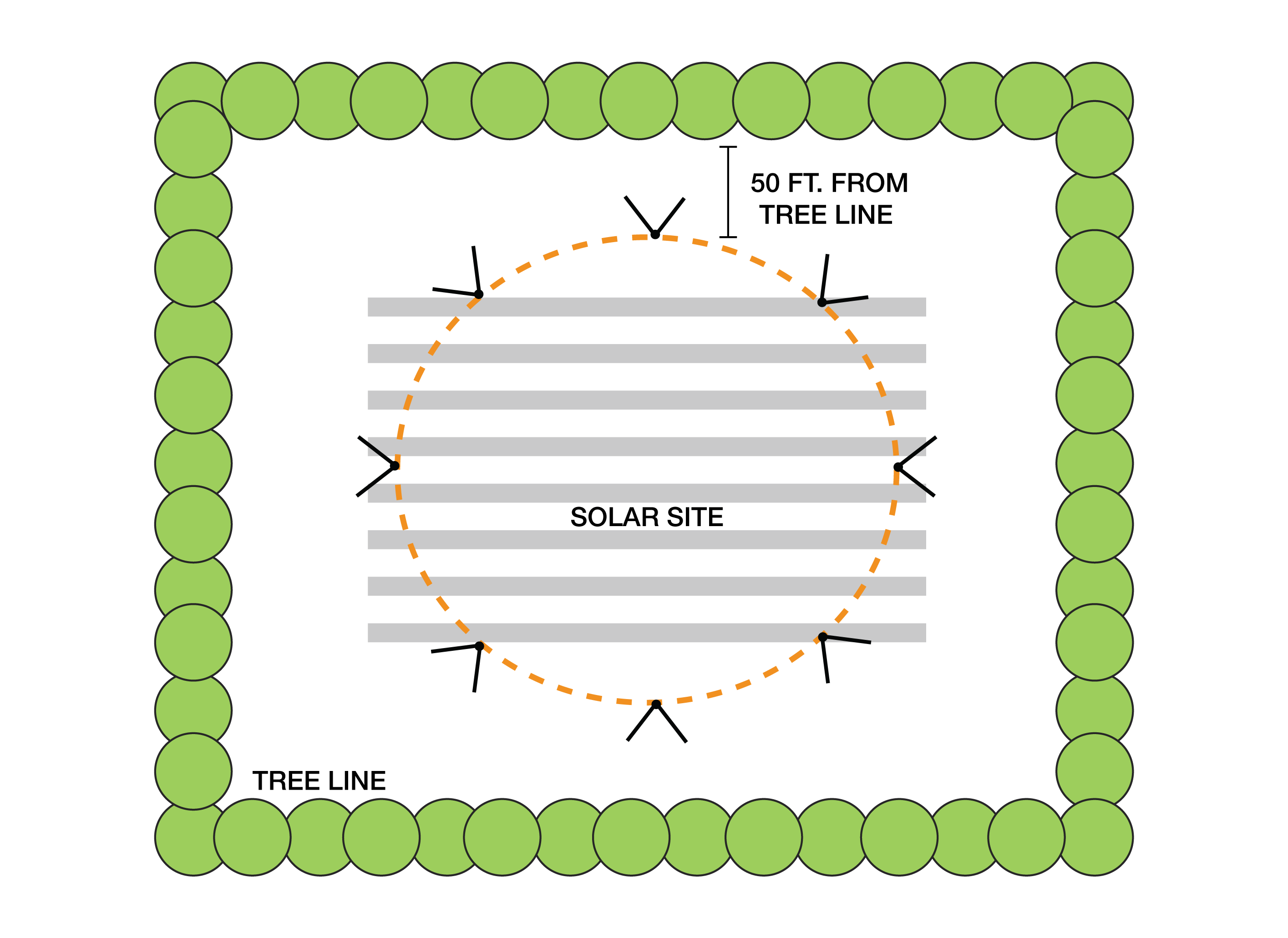
Approx. 30 degrees facing toward the tree line and away from the center of the site (NO HORIZON SHOULD BE VISIBLE)
Do not include sky in view or resulting image
Flight area:
Flight should be flown in a circle around entire perimeter of array and 50 ft inward from the bordering obstructions
Overlap:
10% overlap

OUTWARD OBLIQUES
Altitude:
Altitude: Approx. 100 ft above treeline
Gimbal pitch:
Oblique
-15.0 to -45.0 degrees from horizon
Overlap:
70% overlap
Updated 5 months ago
